Character-Recognition Application for BREW "Recog" -3/4-
BREW and Bitmaps
IBitmap Interface
The IBitmap interface is used when handling bitmaps in BREW.
Since Recog needs to analyze each pixel of the camera's bitmap images, the IBITMAP_GetPixel function seems to be suitable for this application.
However, IBITMAP_GetPixel cannot be used because the BREW emulator does not support it.
DDB and DIB
With no compatible APIs available, direct access to the buffer that contains bitmaps is the only solution.
There are 2 kinds of BREW bitmaps, DDB and DIB.
DDBs are machine dependent bitmaps used within the handset hardware; they lack portability.
A DIB is not machine dependent, its data structure is the same in all handsets. Therefore, Recog will use DIB for direct access to the bitmap.
* BREW systems expect DDB bitmaps, but a mutual conversion function exists.
Structure of DIB
In BREW, a DIB is represented by a IDIB structure. ( See the code below )
OBJECT(IDIB) {
  AEEVTBL(IDIB) *pvt;
  IQueryInterface * pPaletteMap;
  byte * pBmp;
  uint32 * pRGB;
  NativeColor ncTransparent;
  uint16 cx;
  uint16 cy;
  int16 nPitch;
  uint16 cntRGB;
  uint8 nDepth;
  uint8 nColorScheme ;
  uint8 reserved[6];
}
The preceding definition's important data members and their meaning are in the next table.
| Member | Meaning |
|---|---|
| cx | Width of the bitmap |
| cy | Height of the bitmap |
| nDepth | Color depth |
| nPitch | Pitch above the buffer |
| pBmp | Pointer to the buffer |
About nPitch
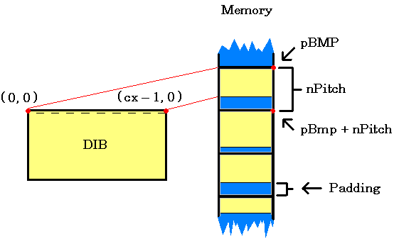
An image is a 2-D matrix, but it must be stored in 1-D memory. This is achieved by allocating slots of memory of constant size ( nPitch ) for each line of image data, and storing the lines of data progressively.
The image's point ( 0,0 ), located at its top left corner, is its starting point in memory ( pBmp ). A single line of data starting from pBmp ( 0, 0 ) until ( cx -1, 0 ) is continuously stored in one memory location of size nPitch.
The starting point of each line ( 0, y ) corresponds to the memory location pBmp + y * nPitch.
The lines of image data are not all the same size, but they are allocated equal amounts of memory. Hence, there is usually some unused portion of memory ( padding ) at the end of each slot.
The second line of data starts at the point ( 0, 1 ), pBmp + nPitch in memory, and is continuously stored until the point ( cx - 1, 1 ).

This process is repeated until the end of the last line of data.
Two Types of DIB

The two images are actually the same, except that they are vertically reversed
These images illustrate the two techniques of data storage available in DIB: lower order byte, and upper order byte. The difference between the two is in the sign of the nPitch data member of the IDIB structure.
In the image on the left, the top side is the lower order byte, nPitch has a positive value and these factors produces the resulting image orientation.
But programmers do need to worry about the two DIB formats to access pixels.
In every line of image, the size of a pixel is saved as the nDepth data bit. So the data for the point ( x, y ) is in the [ x * nDepth ] bit, counting from [ pBmp + y * nPitch ].
SophiaFramework UNIVERSE uses SFBDIB class member functions instead of the IDIB structure.


